OV7670-FIFO + MSP430 Launchpad
Since posting my previous blog entry on the ov7670 camera sensor, I've received an increasing amount of comments and questions about the module. I'm happy that my little experiment may have been some help to people, and I'm sorry I haven't been able to answer all the questions.
Some of the questions have been about the FIFO version of the module, while my experiments were done with the non-FIFO version. I now have the FIFO version as well, so it's time to try it out!
The basic difference between these modules is this:
Basic camera module. You have to deal with bare (digital) video signals, which require processing power to catch properly. You also need some memory for storing the video frame. A good way using these would be to clock the data directly to a memory (or with some digital logic between), like what the FIFO version of the module is doing.
ov7670 with FIFO This module adds an AL422 FIFO memory chip, and the module is designed so that the video data can be clocked directly to the FIFO. You can read the FIFO as slowly as you like, and don't need a big memory of your own for the data. This module also provides it's own clock. static/ov7670-fifo-msp430-launchpad/ov7670_fifo_sch_v2.pdf
In my previous experiment I used a quite powerful LPC1769 microcontroller (running at
120mhz with 64KB memory), which was necessary to be able to process the signals in time.
This time however, thanks to the FIFO memory, the heavy hardware requirements are gone. For this reason I thought it might be fun to use the least powerful MCU I have around, which happens to be the MSP430.
MSP430 Launchpad
My launchpad originally came with G2231, but I replaced it with an G2452 for more GPIO pins. I believe newer Launchpads are now shipped with G2553 and G2452.
For a proper application of the camera, my requirements from the MCU are as following:
- i2c support for setting the ov7670 registers
- UART for transferring image data to PC
- 16 GPIO pins, 8 of which are for image data.
Unfortunately the G2452 is lacking hardware UART (USCI), but I adapted a software UART implementation from here.
The UART runs fine at 115200 baud, but it took an evening with the oscilloscope to fix all the quirks I had with it.
As for the GPIO pins, the G2452 indeed has just exactly the amount of pins I need. However, I needed to desolder my 32khz crystal to free the XIN/XOUT pins for GPIO. The P1.3 pin was a bit annoying, because on launchpad it has a debouncing capacitor for the button, but when used carefully, it works fine for toggling the RRST.
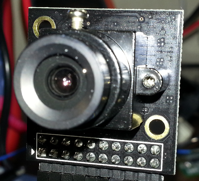
OV7670
 OV7670 connected to MSP430 Launchpad
For initializing the ov7670, I used exactly the same settings as with my previous project. However as a benefit of using the FIFO memory, I could now increase the image size to QVGA (320x240). This was done by changing the COM14, 72h and 73h registers.
One setting that is important to check when using ov7670 with a FIFO is the VSYNC polarity (COM10), since the VSYNC signal is used to automatically reset the write pointer on the AL422 (though this is different with an older version of the module, see here).
Putting the two together
Since the internal pull-up resistors on msp430 seemed to work for the i2c bus, it was possible to connect the camera directly to the launchpad, without needing a breadboard. Here's a list of the connections I used:
 Launchpad-Ov7670 pinouts
Now that the MCU and ov7670 are sorted out, a simple description of the plan is this:
-
On request via UART, capture image to FIFO
- Wait for VSYNC to go high
- Set WEN high
- Wait for VSYNC to go low
- Set WEN low
- Ta-da! There's now an image waiting in the FIFO memory
-
On request via UART, send image to PC
- Reset the read pointer by pulsing RRST and RCLK
- for 320*240*2 times, pulse the RCLK and read the digital pins for image data
Like with the previous project, I'm actually transferring only one line at a time to avoid buffering problems with the PC's UART.
Implementing the functionality turned out to be quite easy and straightforward; much easier than with the non-FIFO version. I think most of the time was spent on battling the software UART and other unrelated stuff.
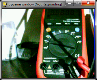
On PC side, I again have a simple python script using pySerial for transferring the image, and pyGame for displaying it on screen. It takes 38 seconds to transfer a 320x240 image via the serial connection. Doesn't seem very fast, but consider the fact that it takes even longer for the Mars Rovers to transfer their images!
Conclusion
The FIFO version is definitely the more useful version of the ov7670 module. Since it doesn't require much from the MCU, just a bunch of pins, it seems like it could be very useful for various hobbyist projects. I think the lack of popularity it has so far is only due to the fact that information available on it is a bit obscure and scattered.
I didn't tune the registers on the ov7670 much, because they give me a headache. If you, dear reader, do something cool with them (or the camera in general), I'd love to hear about it!
I'll definitely use the camera for something (perhaps my secret robot project). In a real application I will probably look into using some I/O expander, or simply an MCU with more pins.
Links
I've dumped the source code to github at https://github.com/desaster/ov7670fifotest
I used plenty outside help to get the project done. Here's some links I found useful:
Comments !